


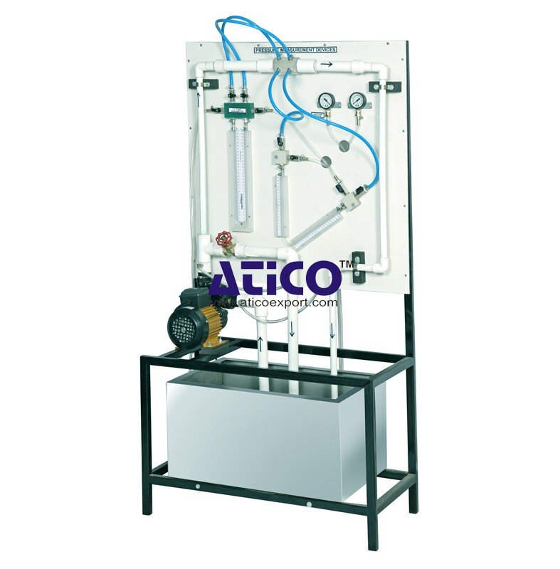
The apparatus consists of converging diverging circular tes...
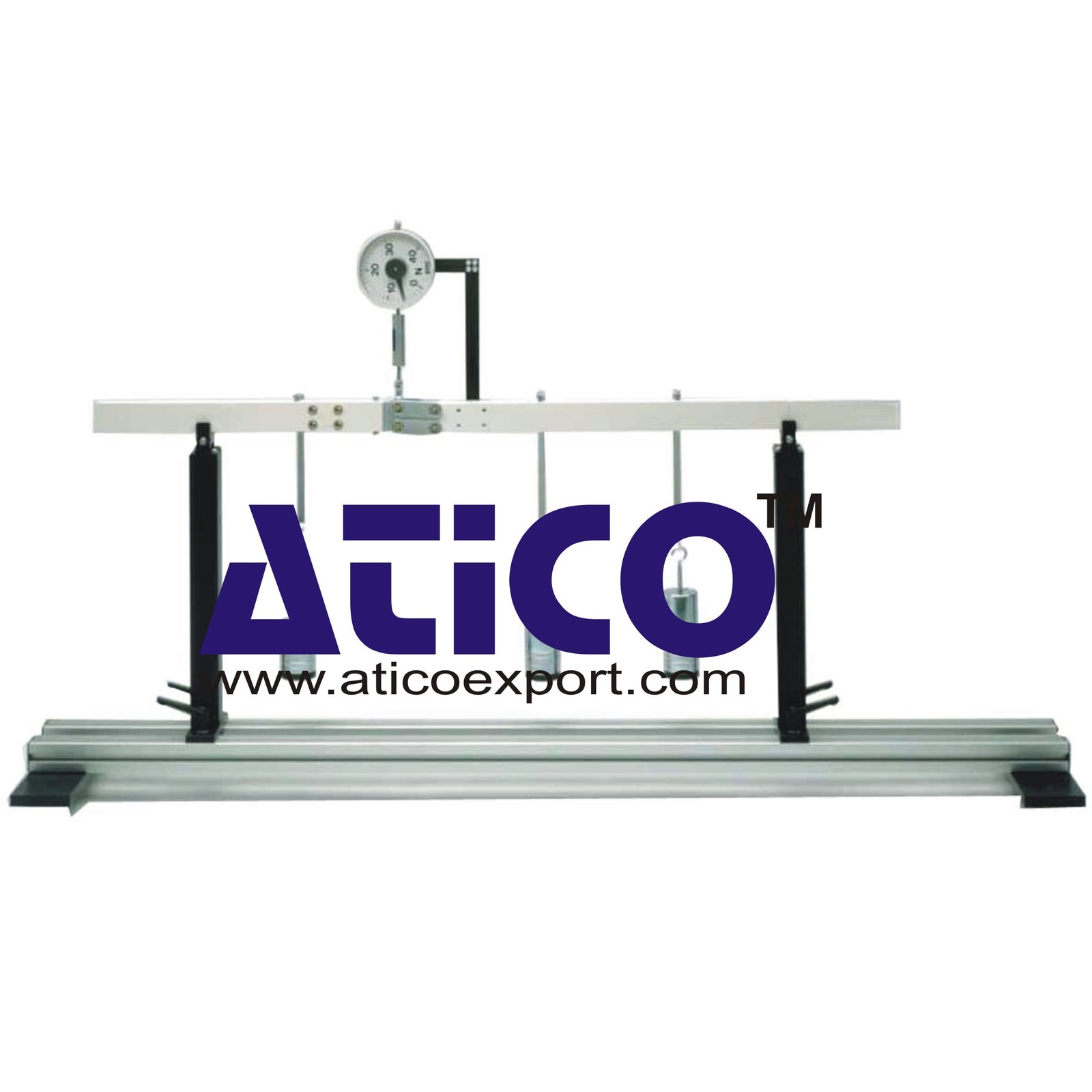
Beam on Two Supports Shear Force Diagram Technical Description: Shear Force Diagram consists of a beam mounted on two supports which is subjected to point loads. The beam is cut at one point. At that...
Shear Force Diagram consists of a beam mounted on two supports which is subjected to point loads. The beam is cut at one point. At that point there is a low-friction hinge with one degree of freedom. The force gauge indicates the internal reaction (shear force) at this point on the beam. An adjuster nut on the force gauge is used to align the beam horizontally and balance out any deflection. The reactions are determined from the static conditions of equilibrium. To investigate the effect of the point loads in the beam, it is notionally split into two segments. Applying the method of sections, the internal forces and moments are plotted onto the two segments and calculated by way of conditions of equilibrium.
1. Investigation of shear force on beam mounted on 2 supports 2. Measurement of shear force in beam by low-friction hinge with 1 degree of freedom 3. Position of hinge at 1/3 span 4. 2 bearing supports 5. Loading of beam by 1 to 3 point loads 6. Force gauge to indicate shear force 7. Adjuster nut for horizontal alignment of beam 8. Storage system to house the components
- total length: 1000mm, span: 800mm Shear force measuring range: -50...+50N
- 3x 1N (hangers), 12x 1N, 9x 5N - max. weight load per hanger: 20N
No Review Yet.
The apparatus consists of converging diverging circular tes...
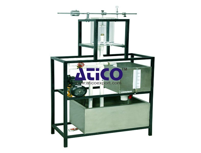
Impact Of Jet Apparatus It can measure the force generated b...
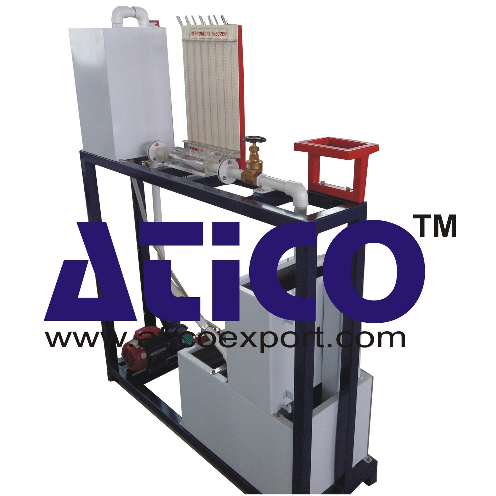
Pipe Friction Equipment Main Losses In Pipe (Losses Due To...
Force Size Gadgets It demonstrates four common types of forc...
Reynold's Apparatus (Laminar And Turbulent Flow Visualistion...
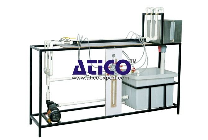
Venturimeter and Orifice Meter Test Rig Venturimeter is use...
Pitot Static Tube Apparatus This instrument comprises of two...
Ice Plant Test Rig Specifications: Compressor - Hermetica...
Copyrights © 2026 All Rights Reserved by Atico

Product
Reviews
add Review
reviews
No Review Yet.