


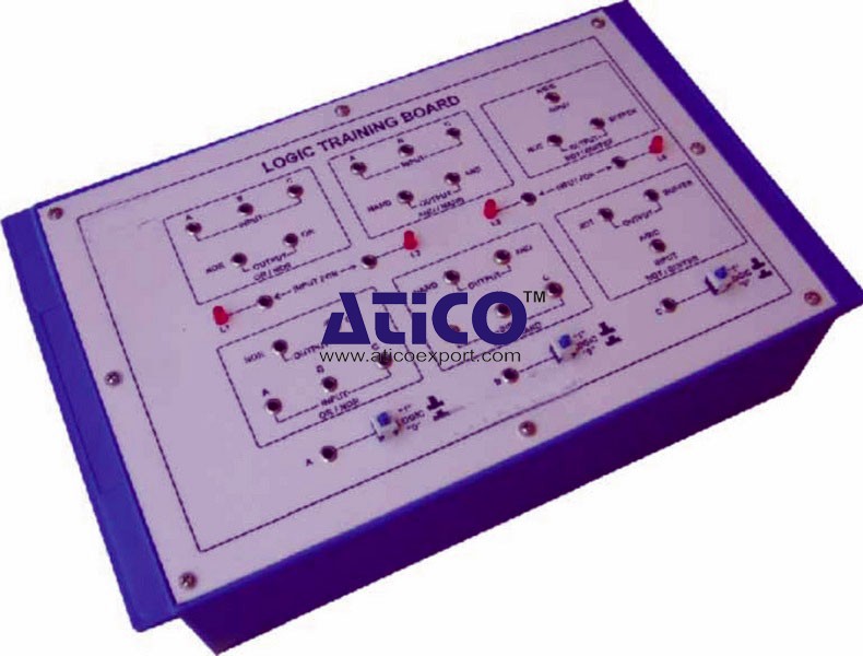
Features: The board consists of the following built-in parts...
Features of Satellite Trainer: • Emulation of path loss at uplink and downlink • Emulation of frequency translation • High RF output power and low noise • PLL synthesizer in Transmitter, Receiver and...
No Review Yet.
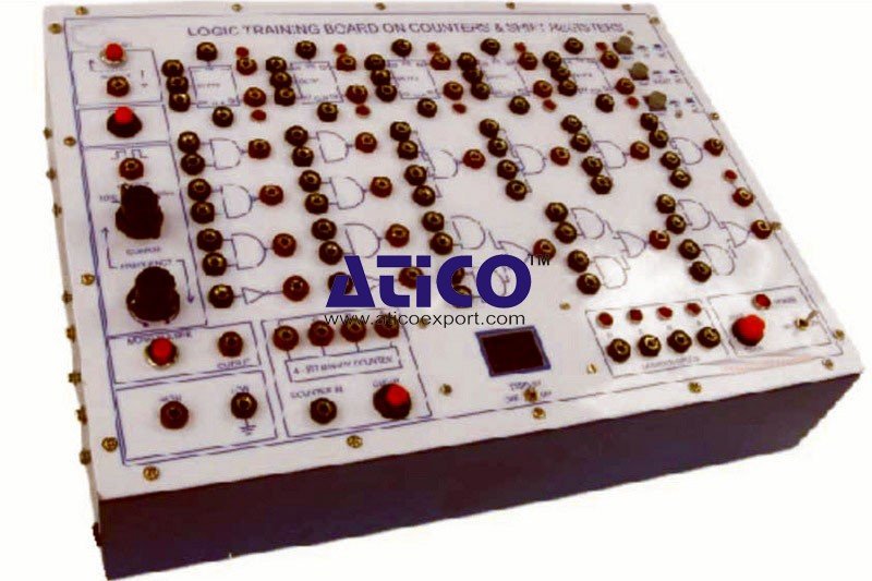
Features: The board consists of the following built-in parts...
Features: The board consists of the following built-in parts...

Features: The board consists of the following built-in parts...
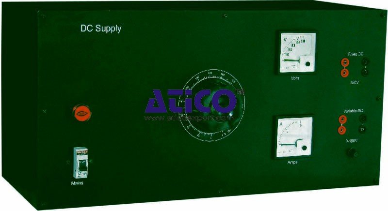
DC Supply is an important device in Electrical laboratories....
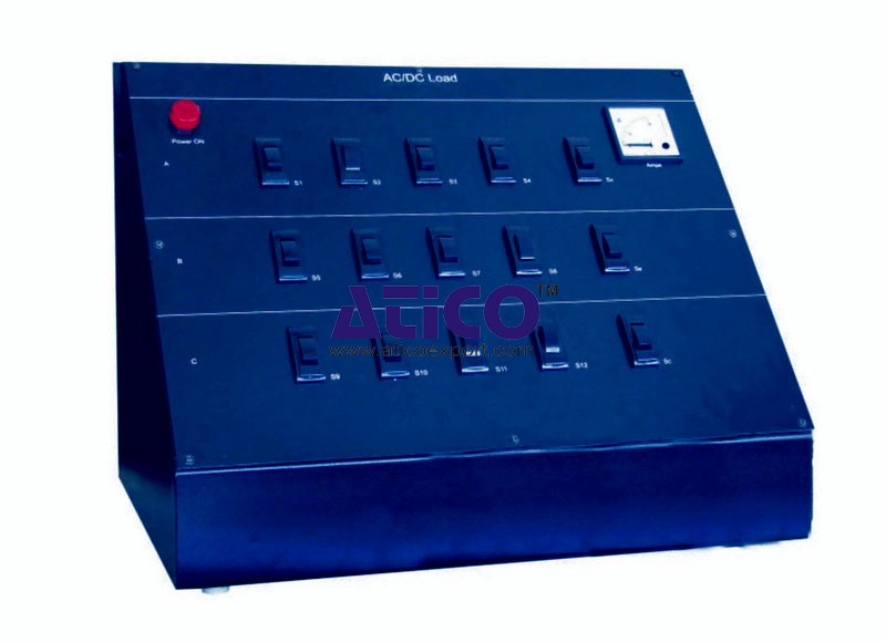
AC/DC Load is an important device in all the Electrical labo...
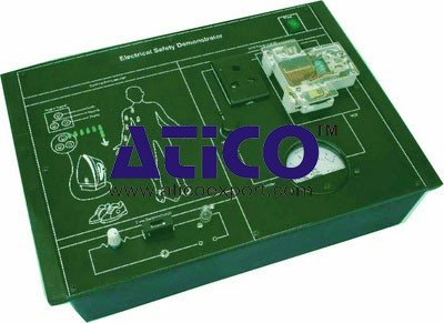
The Electrical Safety Demonstrator is a useful trainer for s...
Single Phase Transformer Lab is an elite training system for...
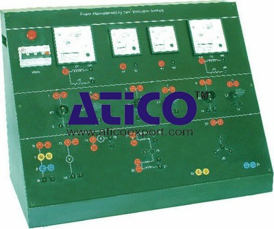
Power Measurement by Two Wattmeter Method Power Measurement...
Copyrights © 2026 All Rights Reserved by Atico

Product
Reviews
add Review
reviews
No Review Yet.