


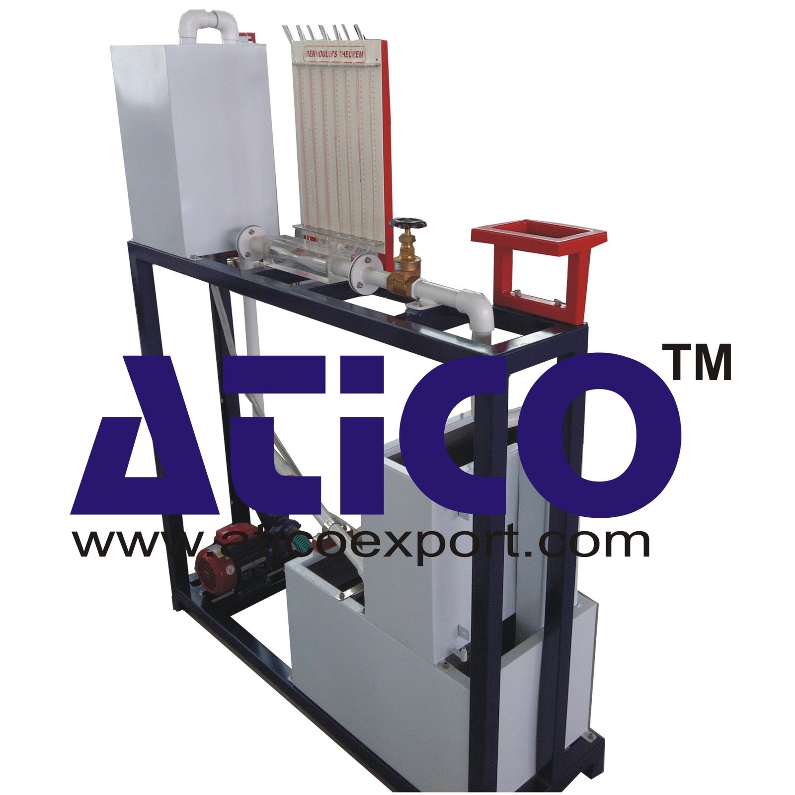
The apparatus consists of converging diverging circular tes...
Horizontal Fluid Friction Plant Teaching Objectives of: Horizontal Fluid Friction Plant Study of the principal elements in an installation of piping. Measurement of pressure losses generated by t...
No Review Yet.
The apparatus consists of converging diverging circular tes...
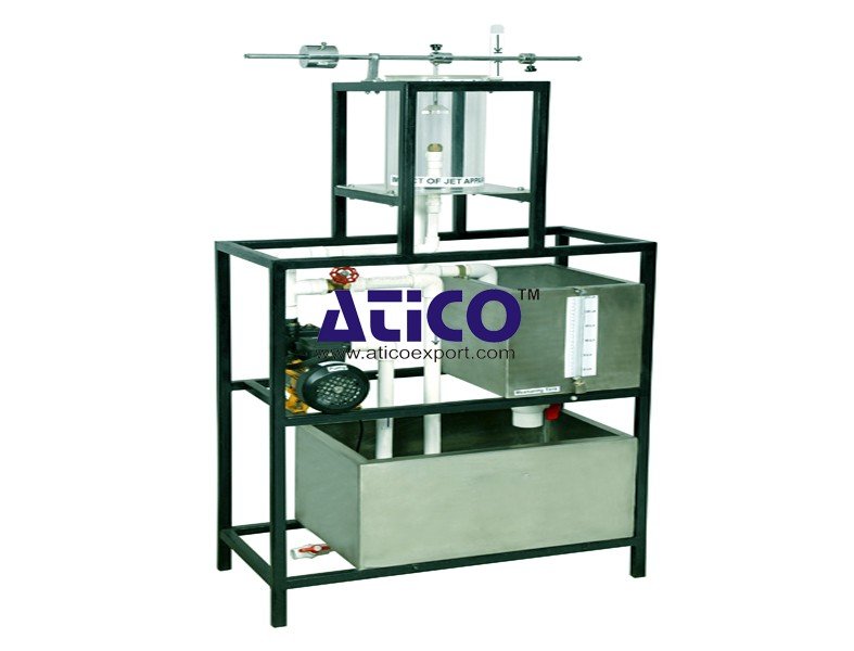
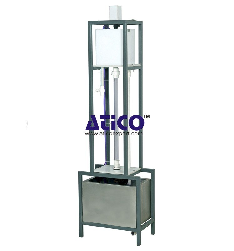
Impact Of Jet Apparatus It can measure the force generated b...
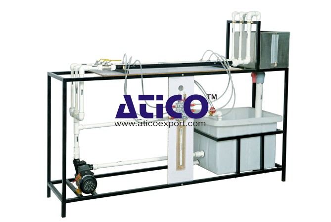
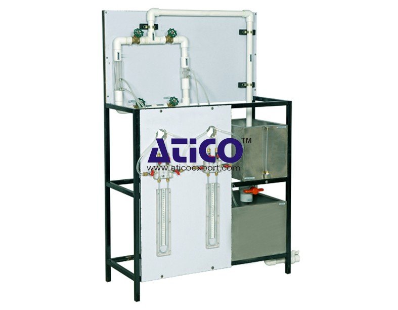
Pipe Friction Equipment Main Losses In Pipe (Losses Due To...
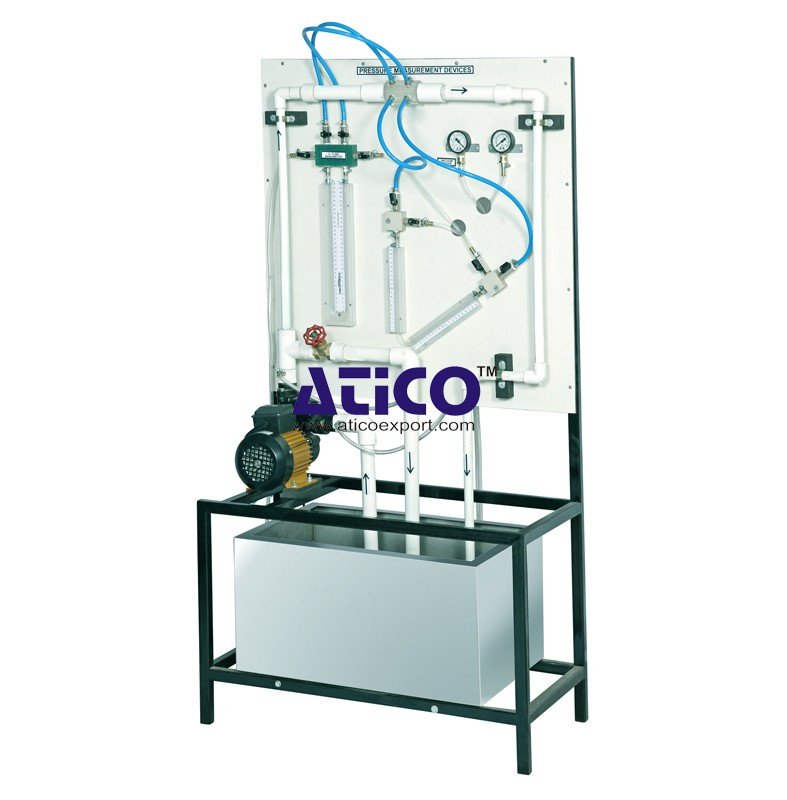
Force Size Gadgets It demonstrates four common types of forc...
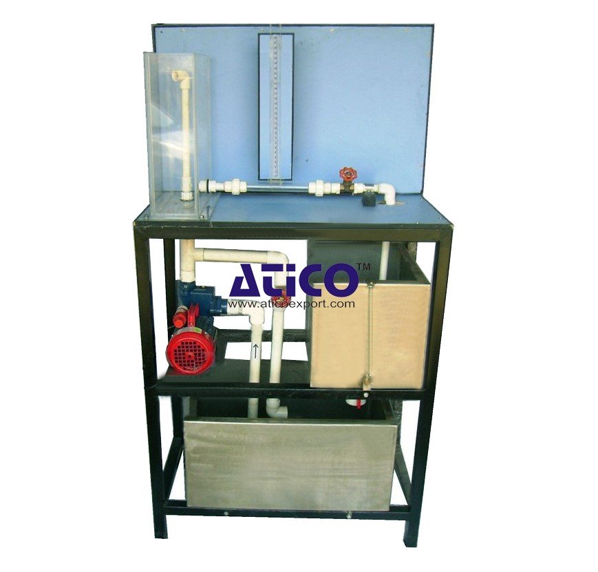
Reynold's Apparatus (Laminar And Turbulent Flow Visualistion...
Venturimeter and Orifice Meter Test Rig Venturimeter is use...
Pitot Static Tube Apparatus This instrument comprises of two...
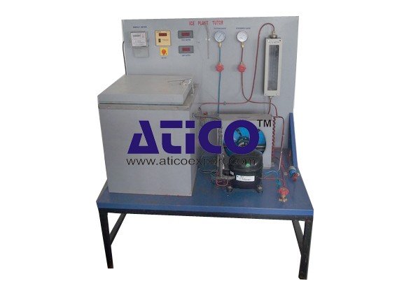
Ice Plant Test Rig Specifications: Compressor - Hermetica...
Copyrights © 2026 All Rights Reserved by Atico

Product
Reviews
add Review
reviews
No Review Yet.