


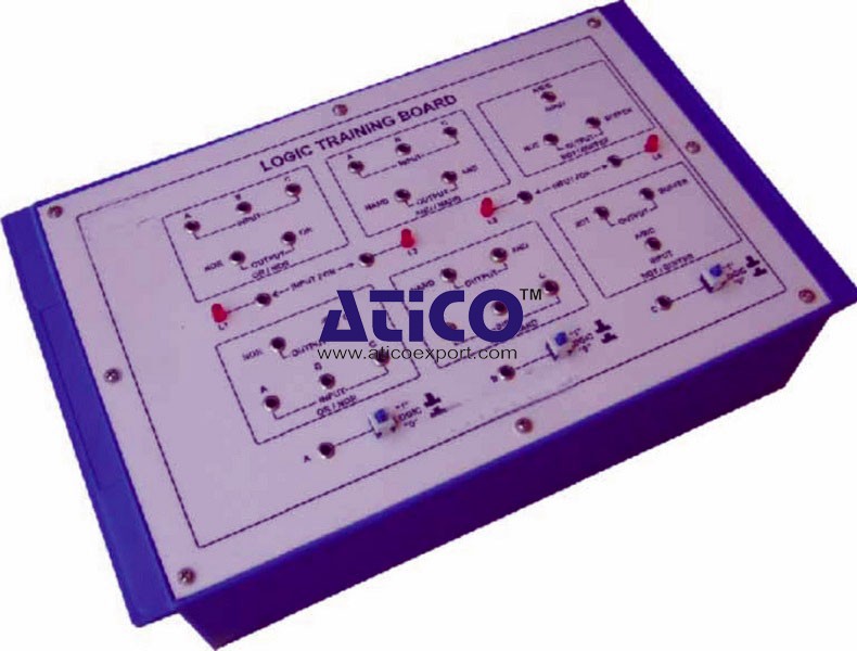
Features: The board consists of the following built-in parts...
Experimental training board has been designed specifically for the study of frequency modulation and demodulation. Practical experience on this board carries great educative value for science and engi...
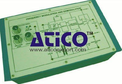
Experimental training board has been designed specifically for the study of frequency modulation and demodulation. Practical experience on this board carries great educative value for science and engineering students.Object:
Experimental training board has been designed specifically for the study of frequency modulation and demodulation. Practical experience on this board carries great educative value for science and engineering students.Object:
No Review Yet.
Features: The board consists of the following built-in parts...
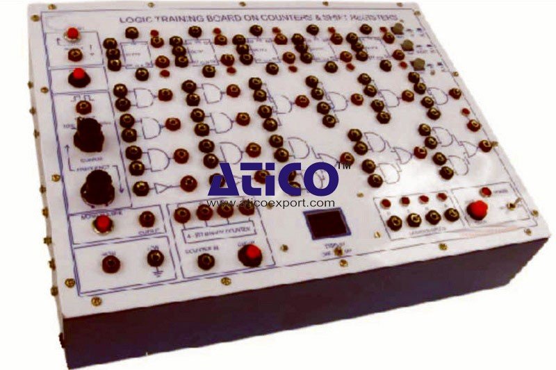
Features: The board consists of the following built-in parts...

Features: The board consists of the following built-in parts...
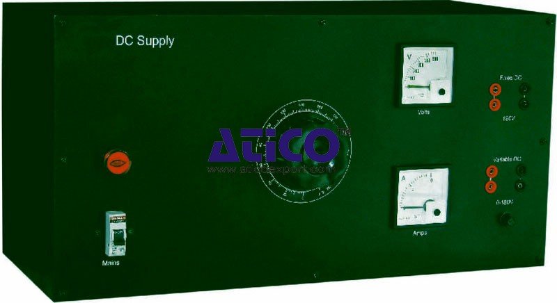
DC Supply is an important device in Electrical laboratories....
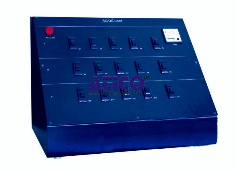
AC/DC Load is an important device in all the Electrical labo...
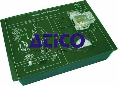
The Electrical Safety Demonstrator is a useful trainer for s...
Single Phase Transformer Lab is an elite training system for...
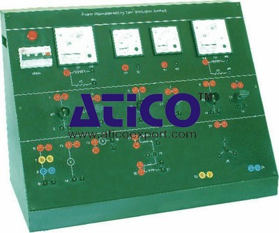
Power Measurement by Two Wattmeter Method Power Measurement...
Copyrights © 2026 All Rights Reserved by Atico

Product
Reviews
add Review
reviews
No Review Yet.