


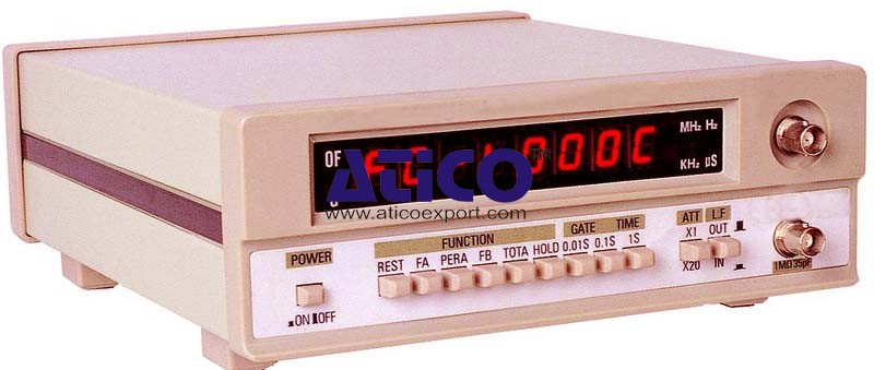
The Frequency Counter offered by us is the instrument that i...
Buckling Behaviour of Bars Technical Description: In technical mechanics, loss of stability is known as buckling. Under the effects of compressive forces, and under increasing load, the axis of the b...
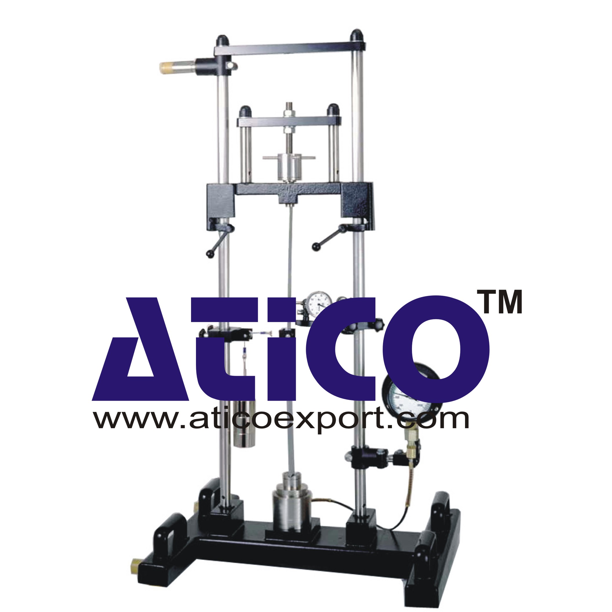
In technical mechanics, loss of stability is known as buckling. Under the effects of compressive forces, and under increasing load, the axis of the bar deflects laterally until it suddenly and violently fails (collapses), even before the fracture point is reached. The stresses in the bar often remain within the elastic range during this process. Investigates the buckling behaviour of bars under various influences. All relevant buckling problems are demonstrated by way of experimentation. For the purpose, one end of a bar is fixed or pinned, depending on the buckling case. A height-adjustable load-carrying cross-arm and a hand-operated spindle are used to apply compressive force to the bar. An axial bearing between the spindle and the bar support prevents torsional loading of the test bar. A hydraulic load cell measures the applied force and indicates it on a pressure gauge. The lateral deflection of the bar is indicated on a dial gauge. Experiments demonstrate various influences, such as bar lengths, materials and methods of support. A transverse load application device can be used to generate additional shear forces on the test bar. The experimental unit can be operated vertically or horizontally. The load gauge can be rotated 90° to adjust to the chosen option. The various elements of the experiment are clearly laid-out and housed securely in a storage system.
- quantity: 11 - bar length: 350...700mm (max.) - materials: aluminium, copper, brass, steel, GRP
- cross-sections: 10x4mm, 25x6mm, 25x10mm
- force: max. 2000N - stroke: max. 10mm Lateral deflection: max. 20mm Specimen holder bore: d=20mm
- force: 0...2500N, graduations: 50N - deflection: 0...20mm, graduations: 0,01mm Set of weights for transverse load: max. 20N - 3x 5N, 1x 5N (hanger)
No Review Yet.
The Frequency Counter offered by us is the instrument that i...
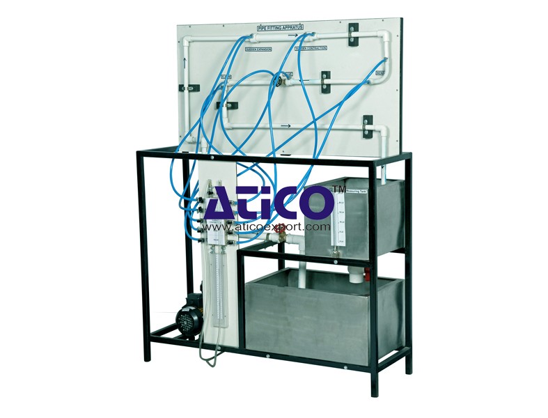
Losses In Pipe To determine minor flow losses(Fittings) in...
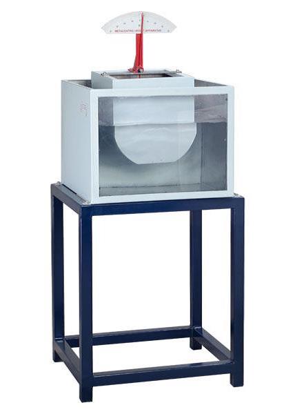
Metacentric Top Equipment Fundamentals of Buoyancy, Metacent...
Notch and Weir Apparatus Notches or Weirs are kept in the p...
Orifice and Mouthpiece Apparatus Both orifices and mouthpiec...
Orifice Meter This equipment is designed to introduce colle...
Flow Measuring Devices Features: Reliability Remarkable s...
Free and Compelled Vortex Equipment The spiraling movement o...
Copyrights © 2026 All Rights Reserved by Atico

Product
Reviews
add Review
reviews
No Review Yet.